This week, my team at Monumental Labs announced the world’s first end-to-end autonomous CNC stone carving system of its kind. On October 5, 2026, Sebastian Marino, James Darby, and I presented it at Embodied AI NYC, hosted by NY Robotics and ZeroSpace Labs in Brooklyn. This post is a written version of our talk: how our system turns a 3D model and a block of marble into a finished sculpture, with no human in the loop.
Why stone, and why now
Civic buildings like Penn Station and Grand Central were once expected to be monumental. Stone carving never disappeared, but rising costs pushed it out of ordinary construction. At Monumental Labs we use machine learning, computational geometry, and optimization to cut that cost by more than 90%: de-extinction, not displacement.
Our goal is zero humans in the loop: a fully automated, end-to-end pipeline built for “lights-out” manufacturing.
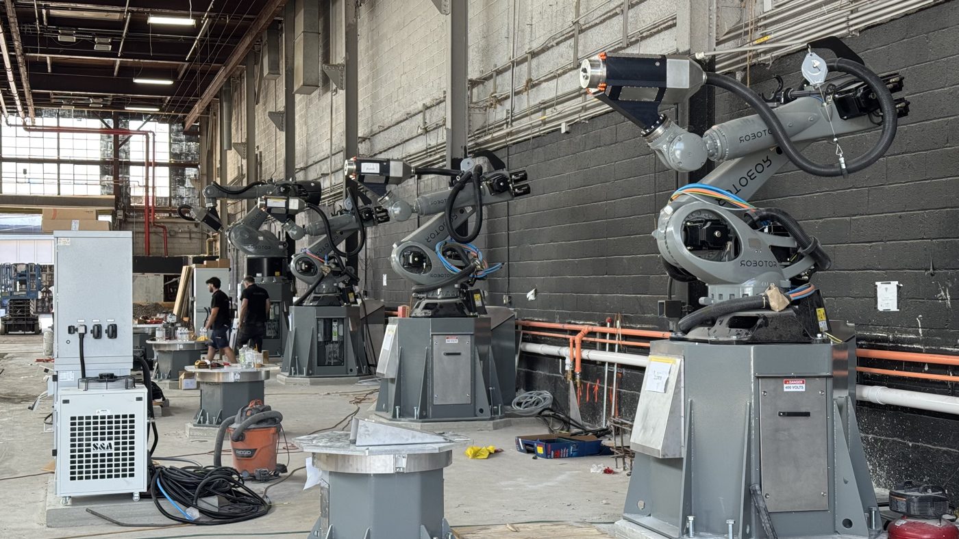
Roughing vs. finishing
Carving happens in two broad phases. Roughing is about material removal rate: getting as much stone off the block as quickly and safely as possible. Finishing is about surface quality: tracing the final form closely enough that what comes off the robot matches the design. The two phases call for different tools, different strategies, and different algorithms.
A magic trick: autonomous roughing paths
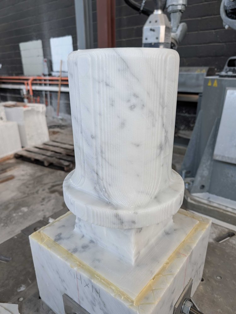
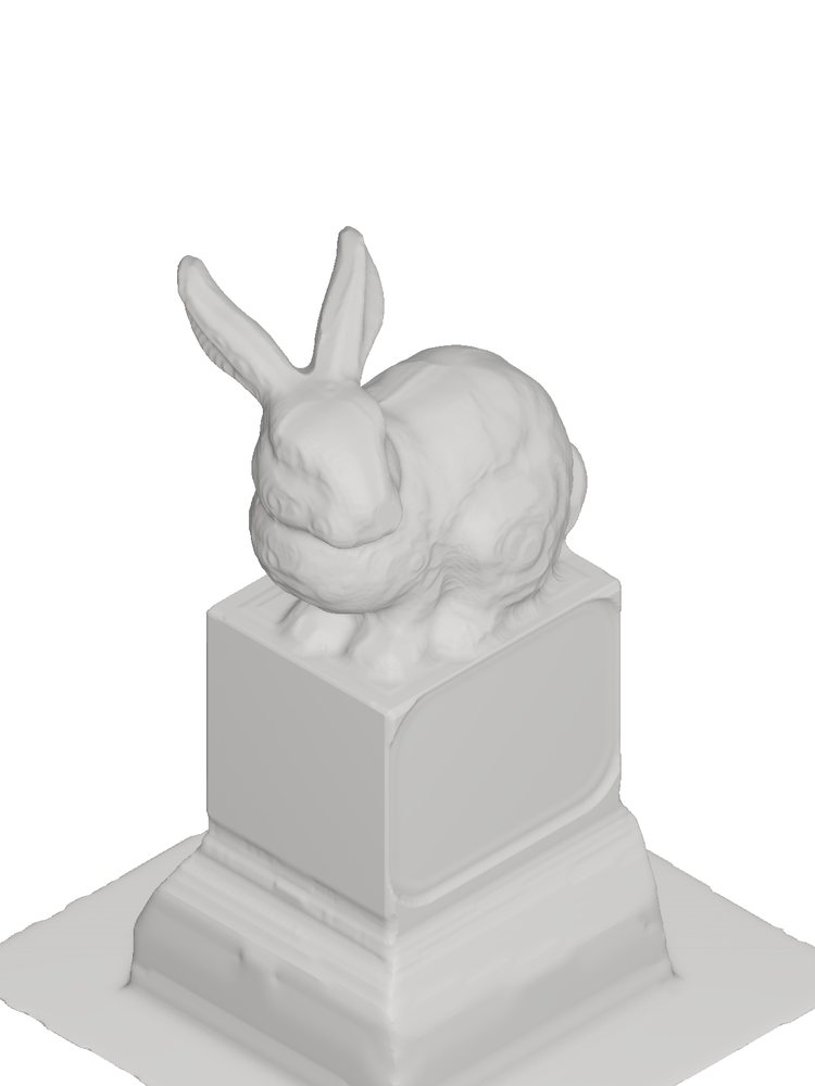
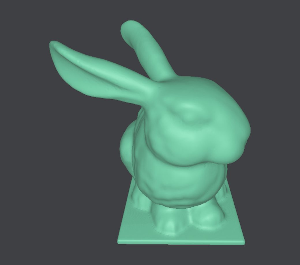
The running example in the talk was a magic trick: start with a block, carve a top hat, and pull a rabbit out of it. The rabbit is the Stanford bunny, a classic test model in computer graphics. We carved the top hat first partly for fun, and partly as a reminder of the magic that happens when robots and art come together.
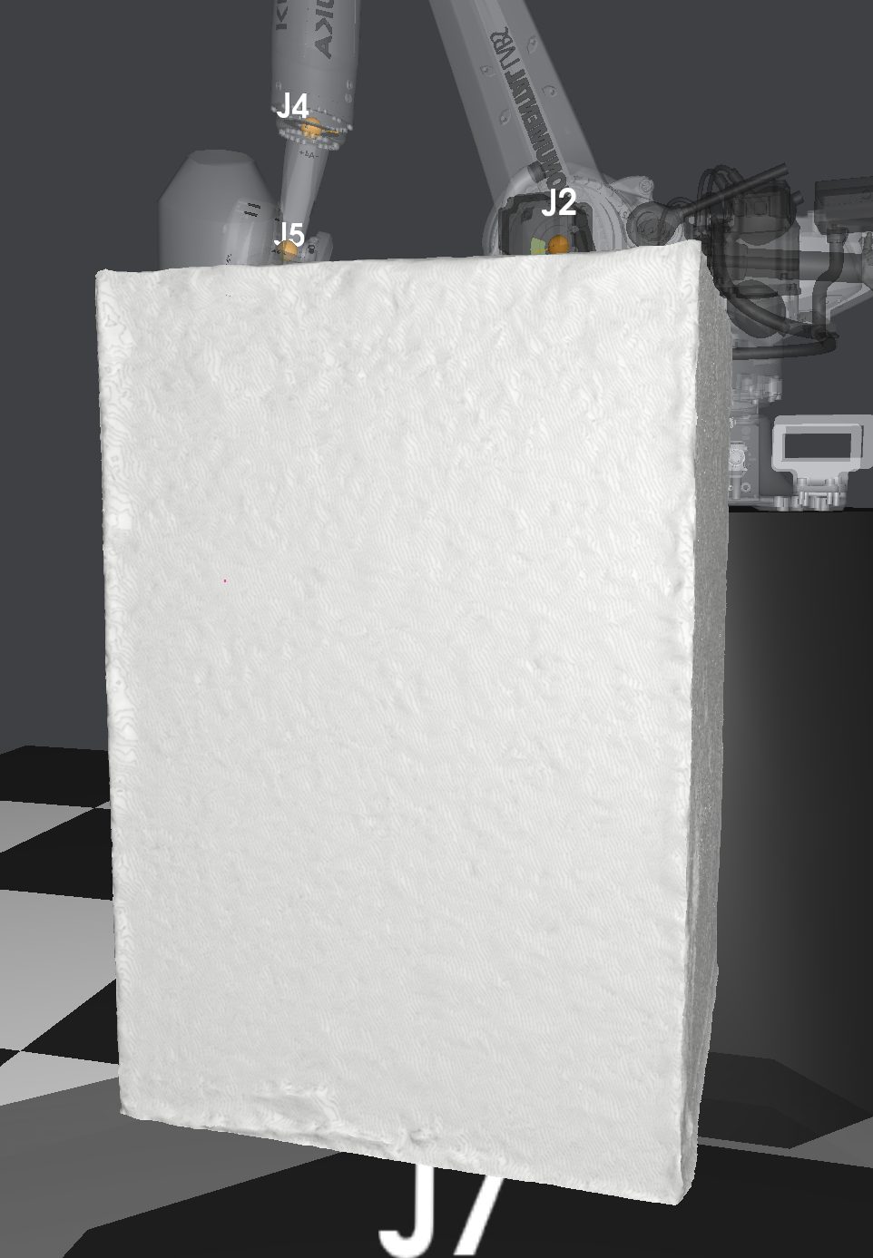 Block
Block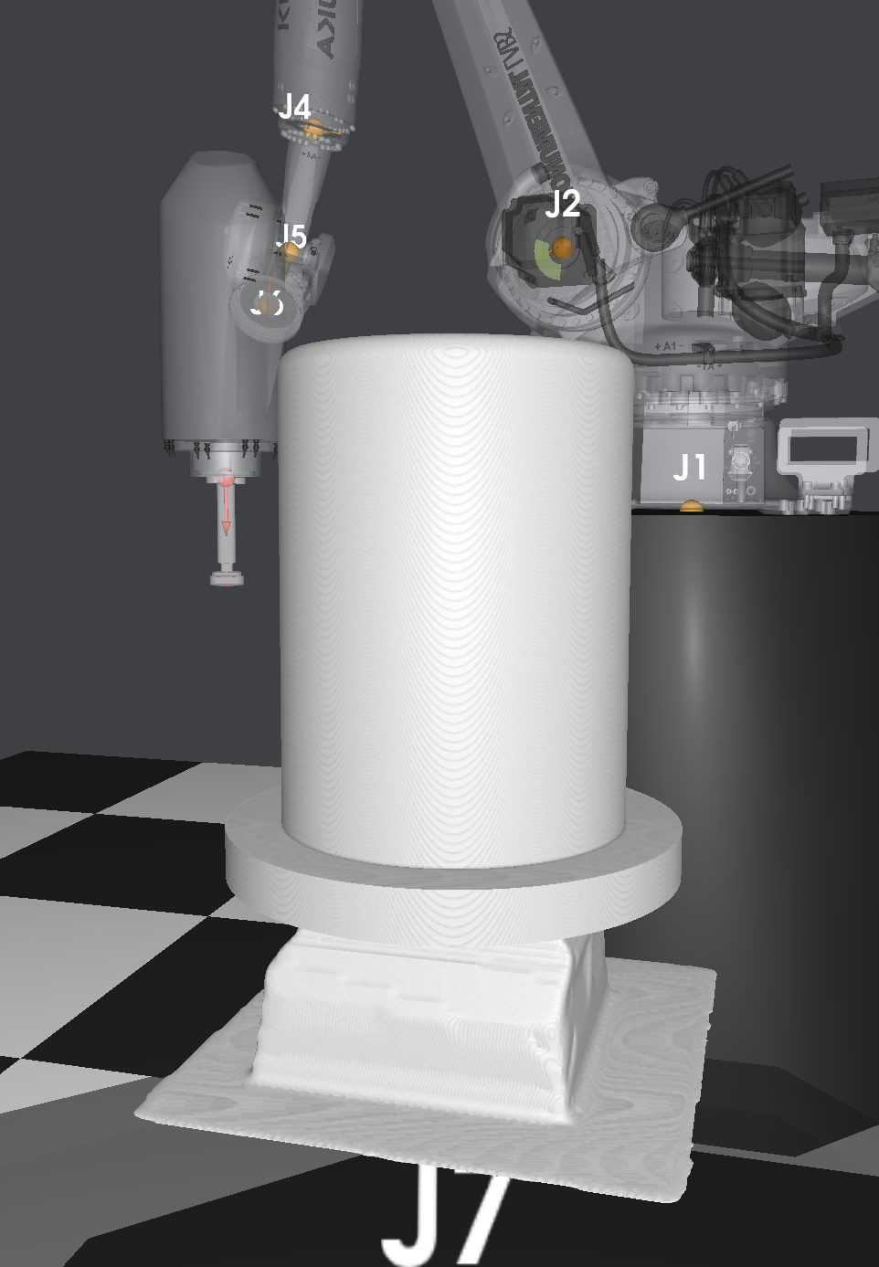 Top hat
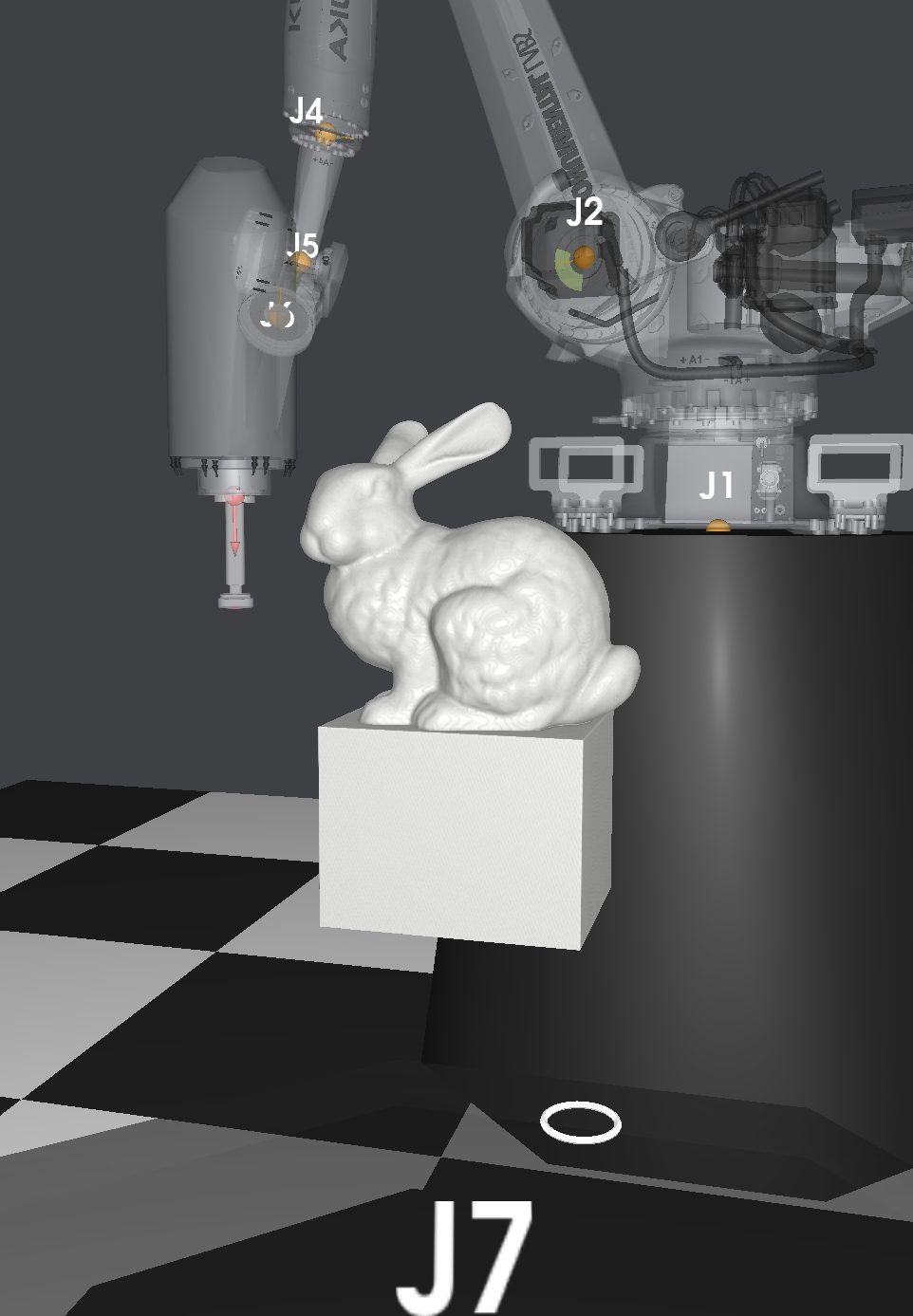 Rabbit
Voxels
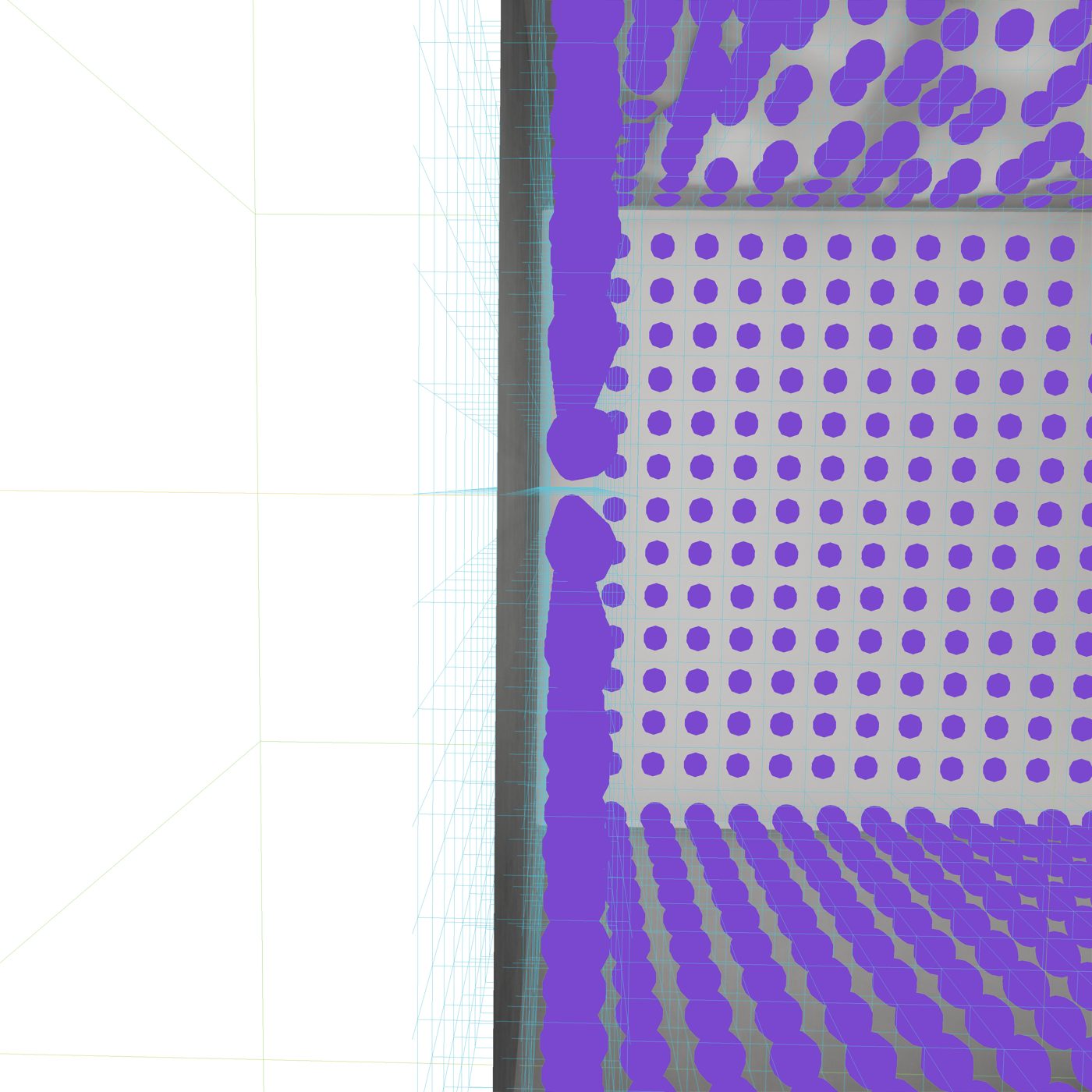
Everything starts with a voxel representation of the stone. Voxels let us accept arbitrary mesh inputs and store them in a sparse data structure, which matters because a dense grid scales cubically with resolution. From the voxels we compute a signed distance field, along with normals and gradients. That gives us a natural basis for constructive solid geometry, which is exactly what subtractive manufacturing is: the stone minus everything the tool has removed.

Bulk material removal
The first job is primary bulk material removal: clearing the large volume of stone between the raw block and the rough shape of the part.
What is a toolpath?
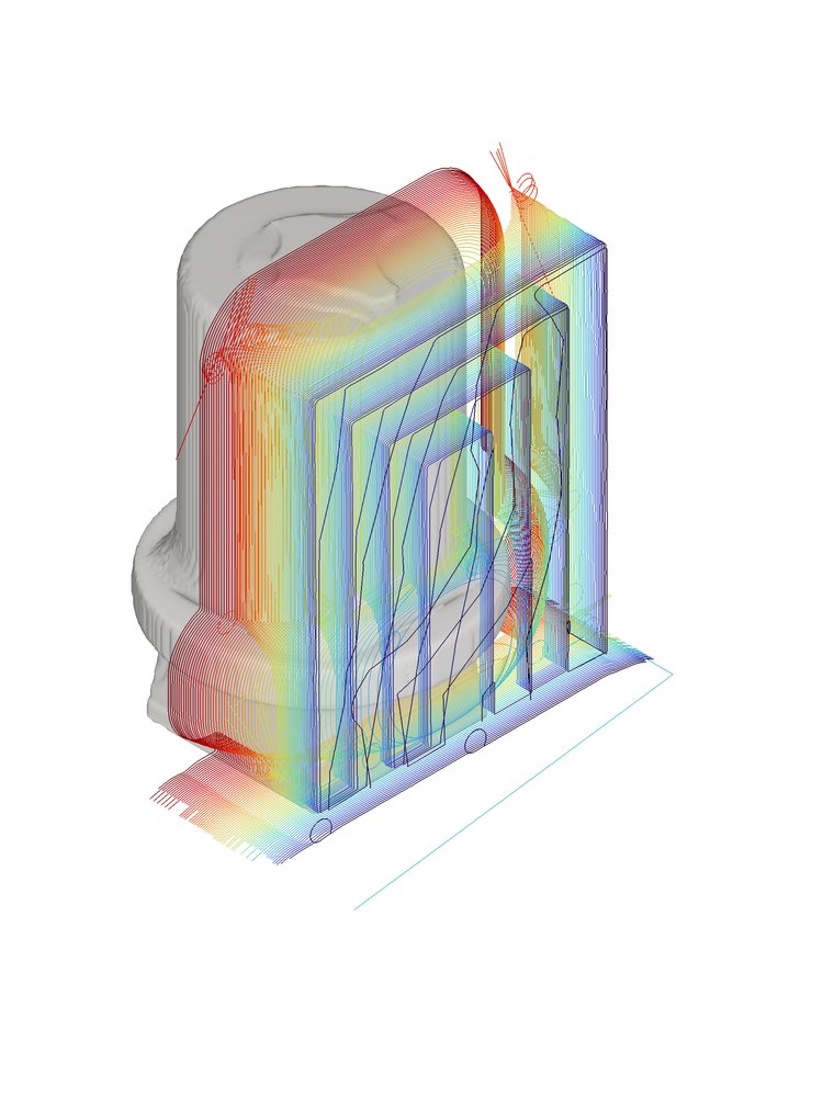
A toolpath is the route the cutting tool follows through the material, eventually written out as G-code that the machine executes point by point. A roughing toolpath has its own anatomy: isoplanar passes that step down through the stone one level at a time, with each pass planned around how much of the tool is engaged in the material.
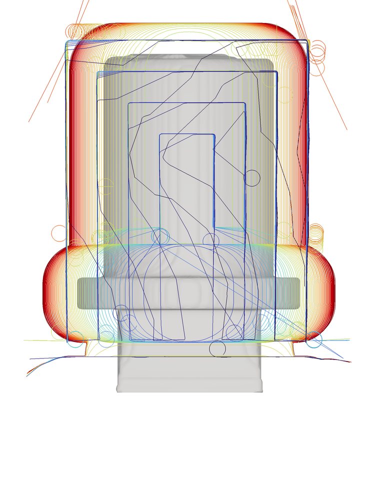
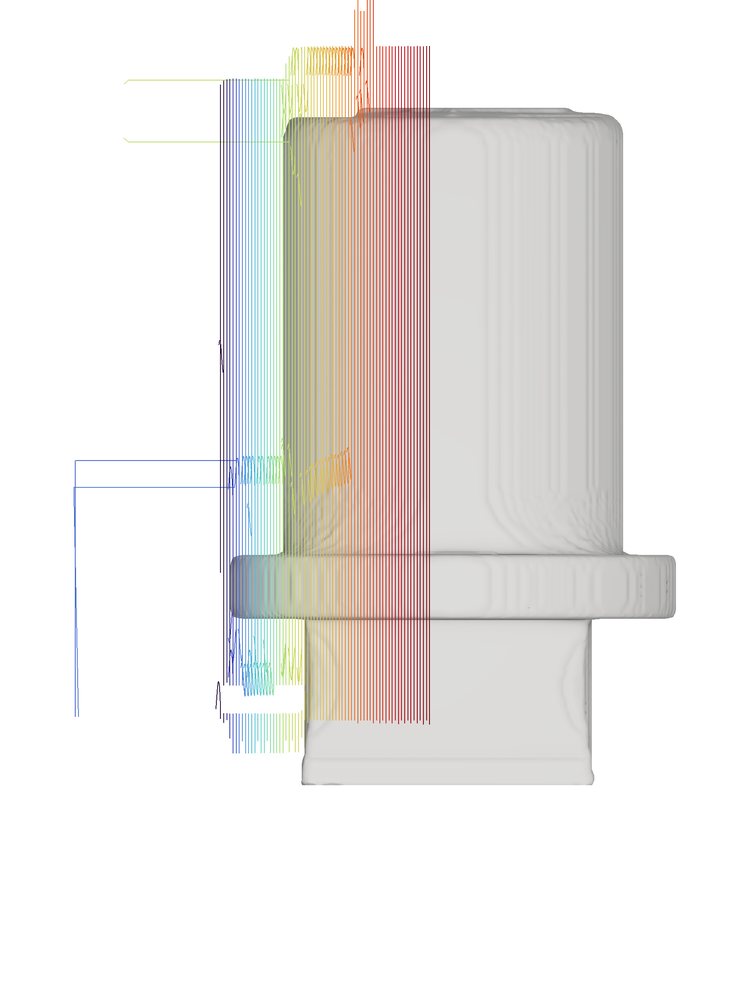
Then the trick continues, and the same machinery starts working the bunny out of the hat.
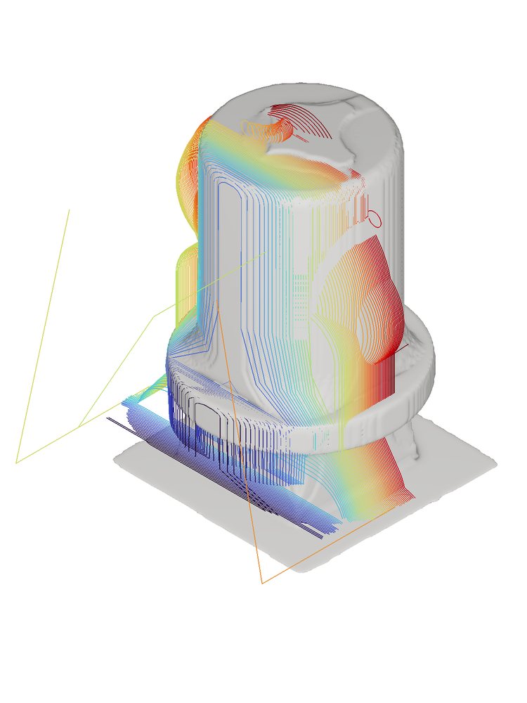
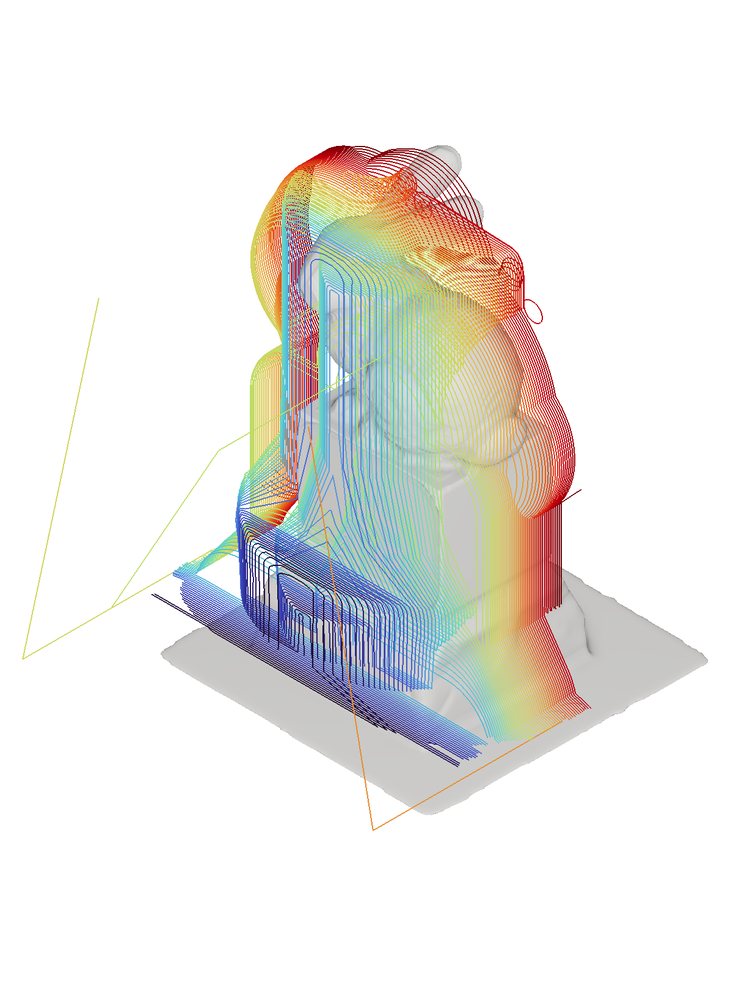
Fine roughing and off-axis roughing
As we get closer to the final surface, we switch to smaller tools and finer passes. Some geometry can’t be reached by cutting straight down, so off-axis roughing cuts along tilted planes to clear material under ears, chins, and other overhangs.
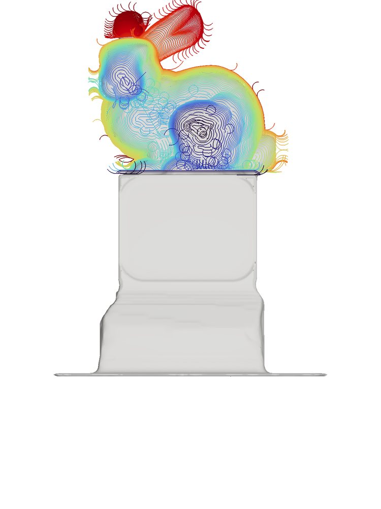
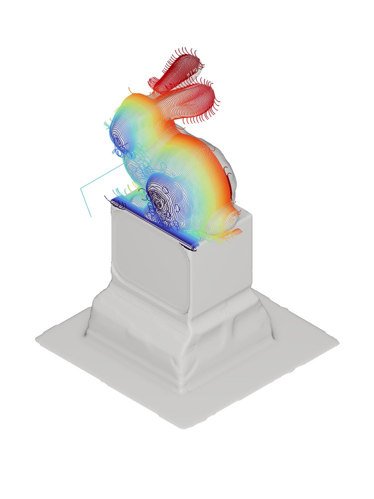
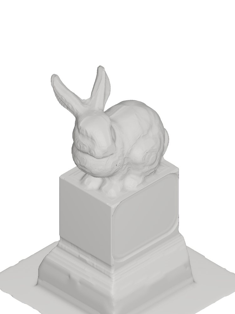
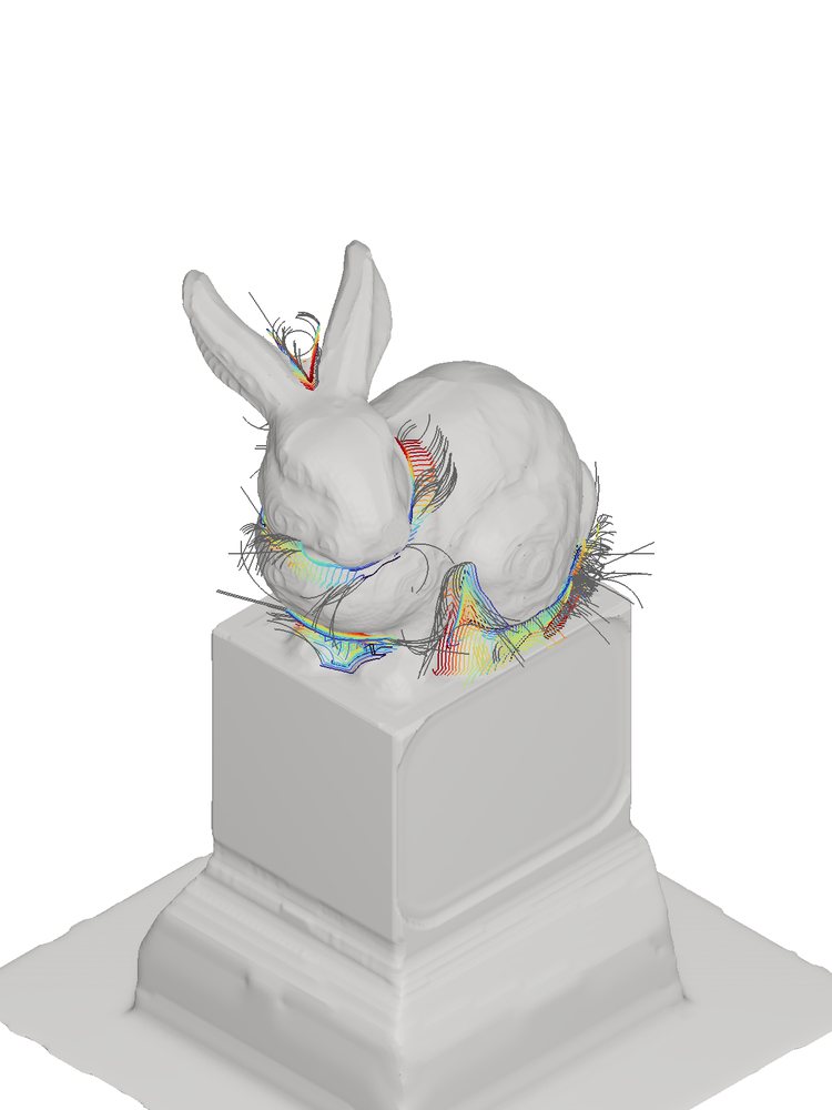
At the end of roughing, the trick is complete in real stone: block, top hat, rabbit.
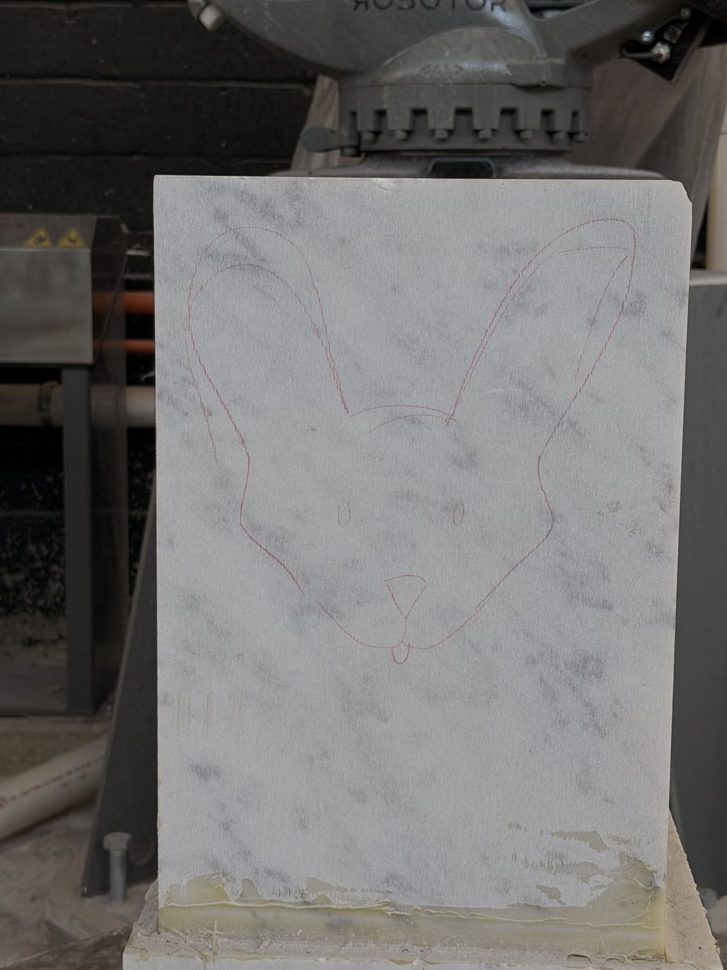 Block
Block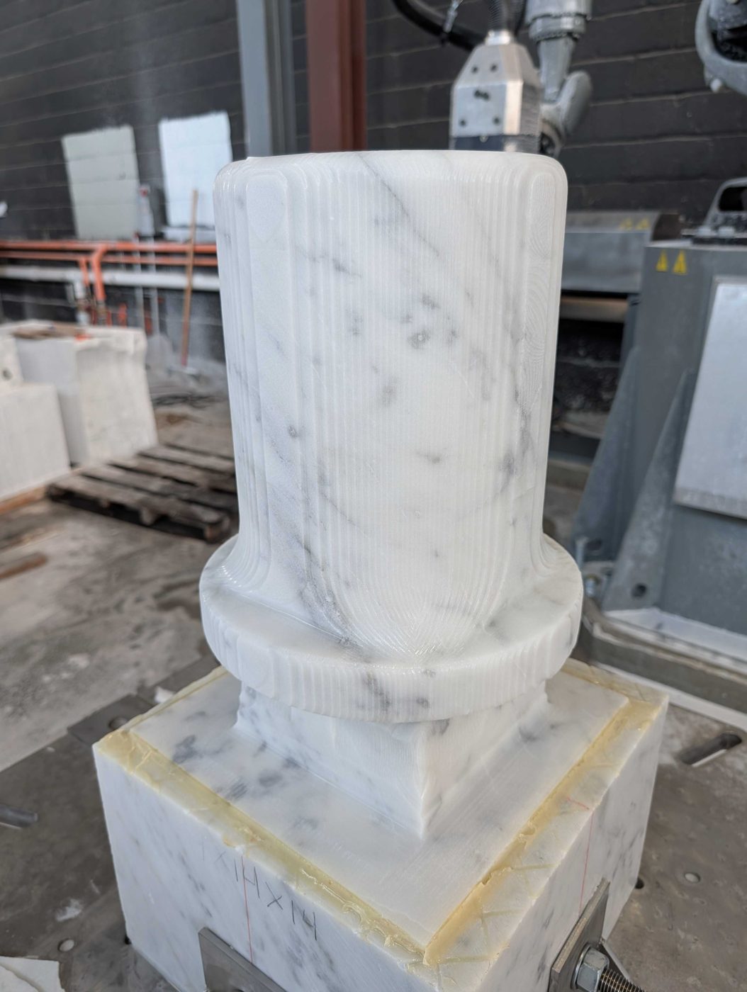 Top hat
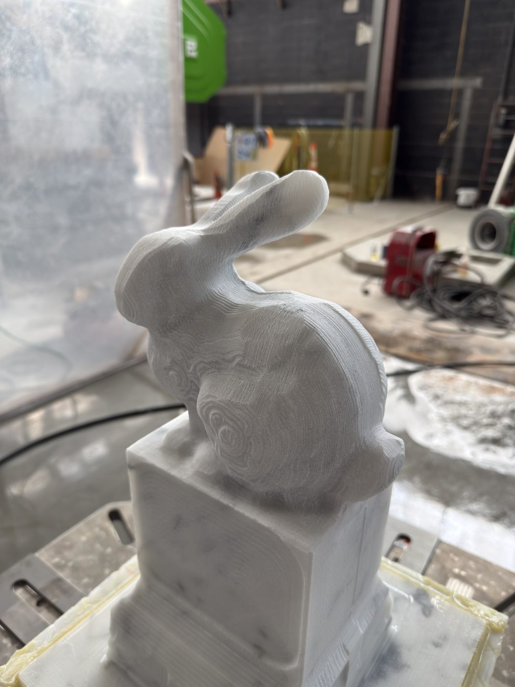 Rabbit
How can a robot finish a sculpture with no human in the loop?
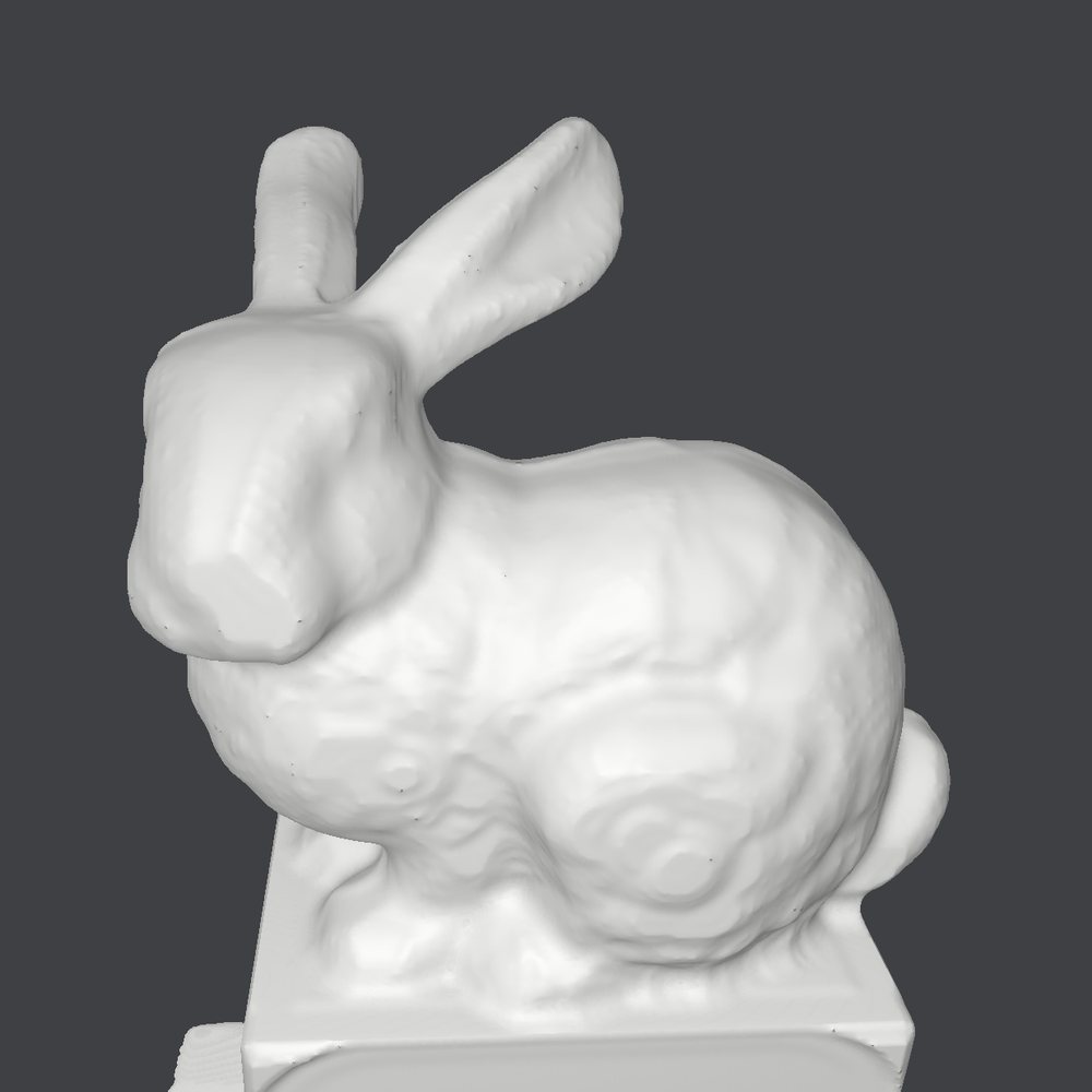
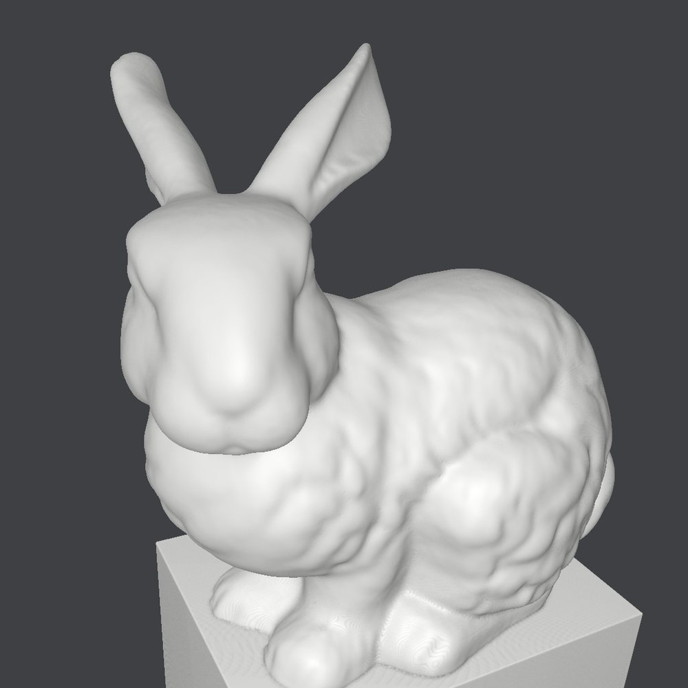
Finishing is where the problem gets hard. The system takes two inputs: the simulated output of roughing, and the target design model. Its job is to close the gap between them.
Layering
We use voxel grid dilation and mesh intersection cuts to solve for optimal finishing layers, taking the remaining stone down in a sequence of offset surfaces until the last layer is the design itself.
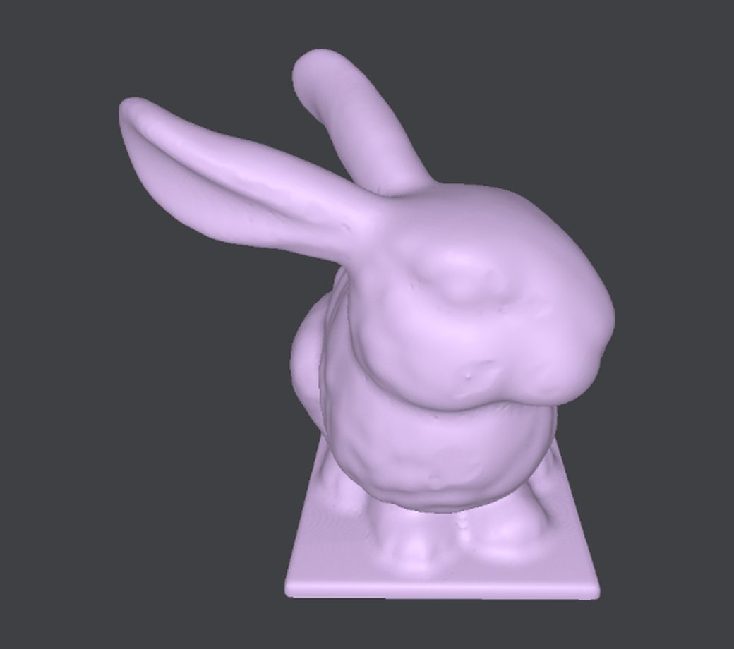
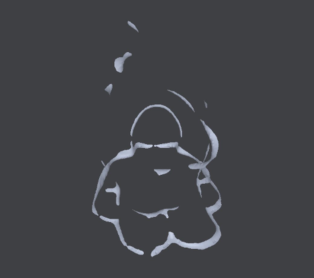
Automated point-cloud segmentation
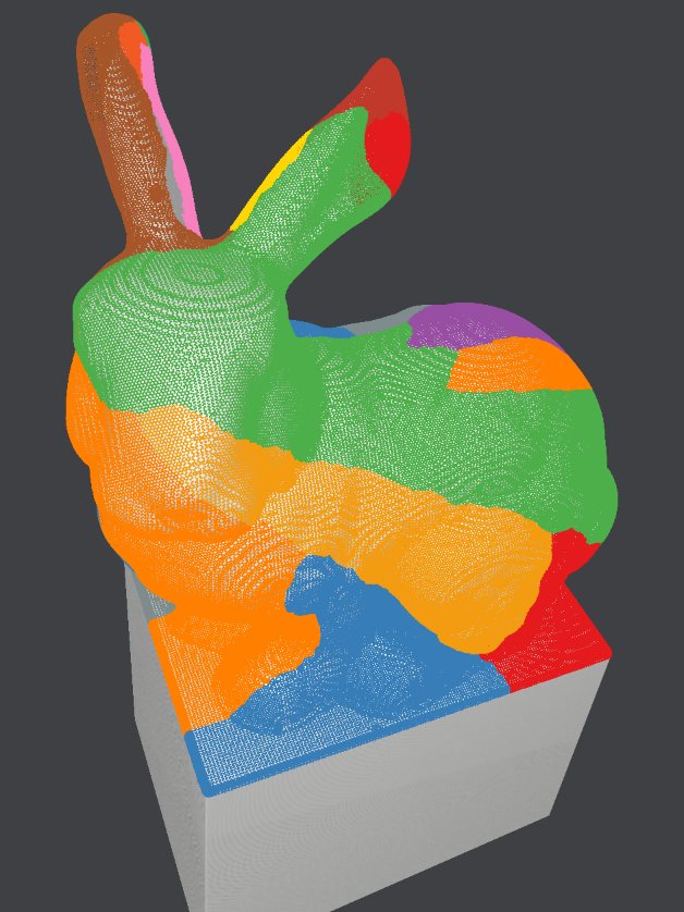
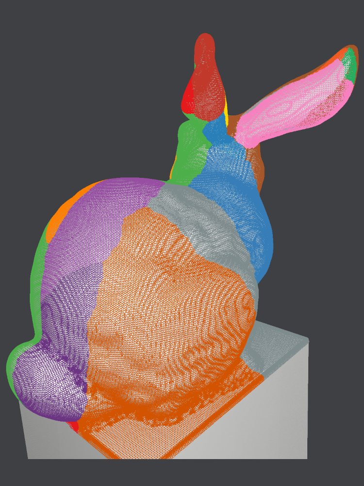
Each layer is then automatically segmented into regions that can be machined together, so every region gets its own toolpath and its own tool orientation.
Generating the toolpath: 3D iso-geodesic distances
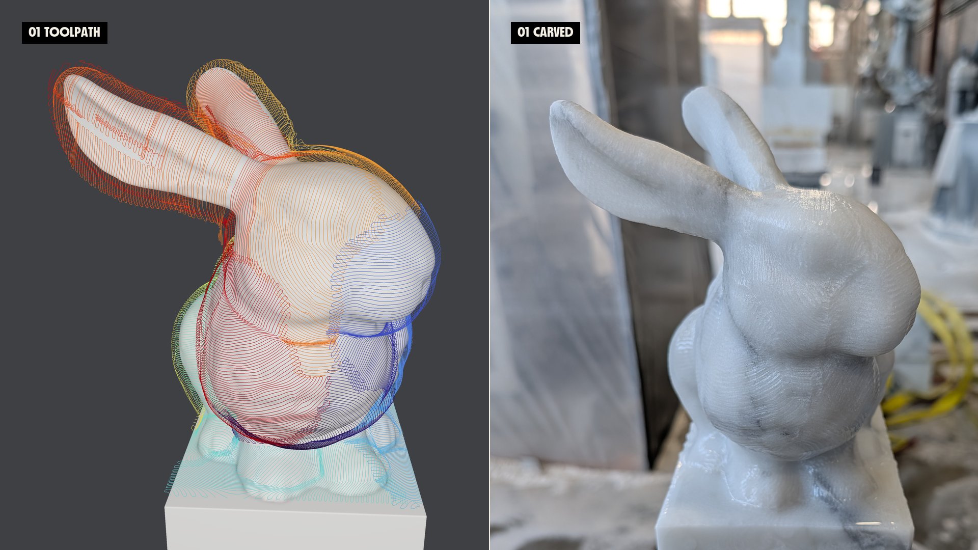
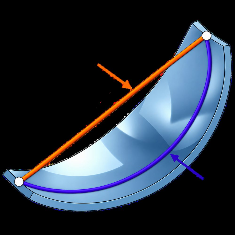
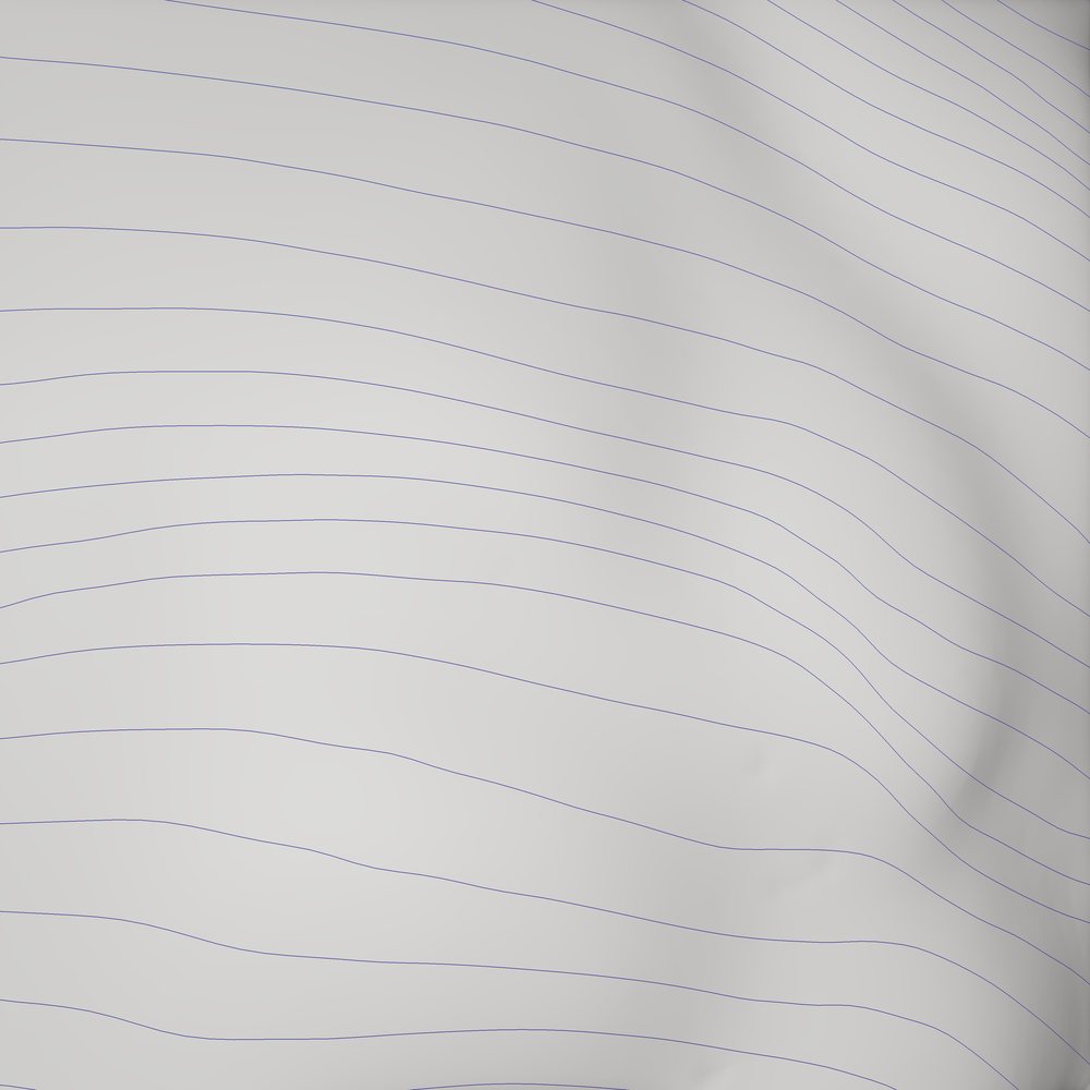
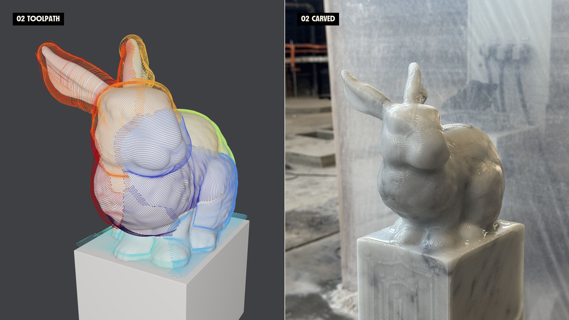
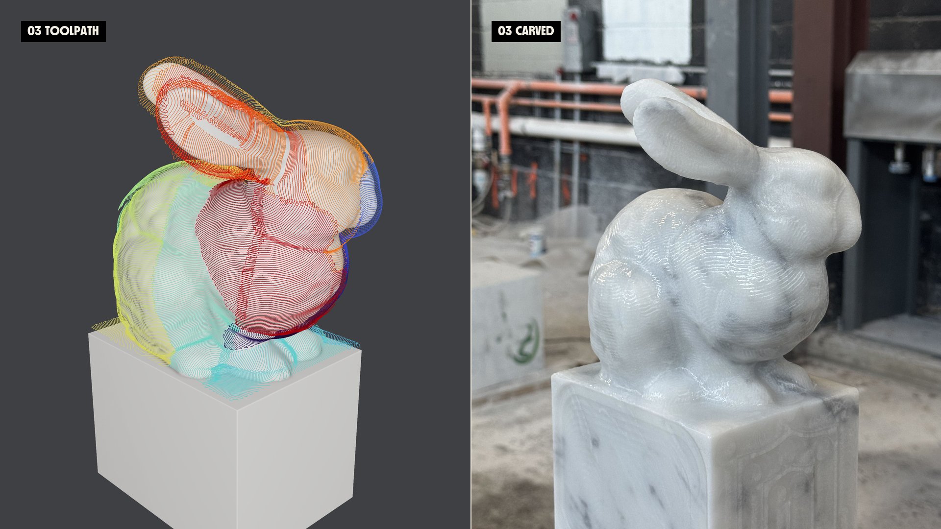
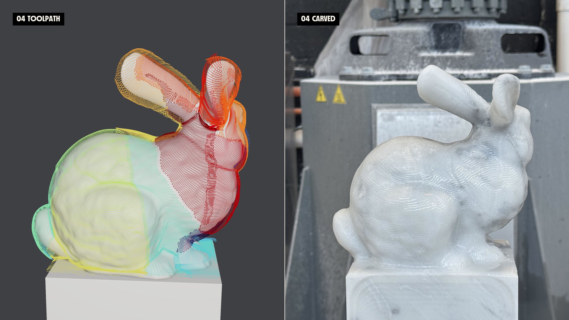
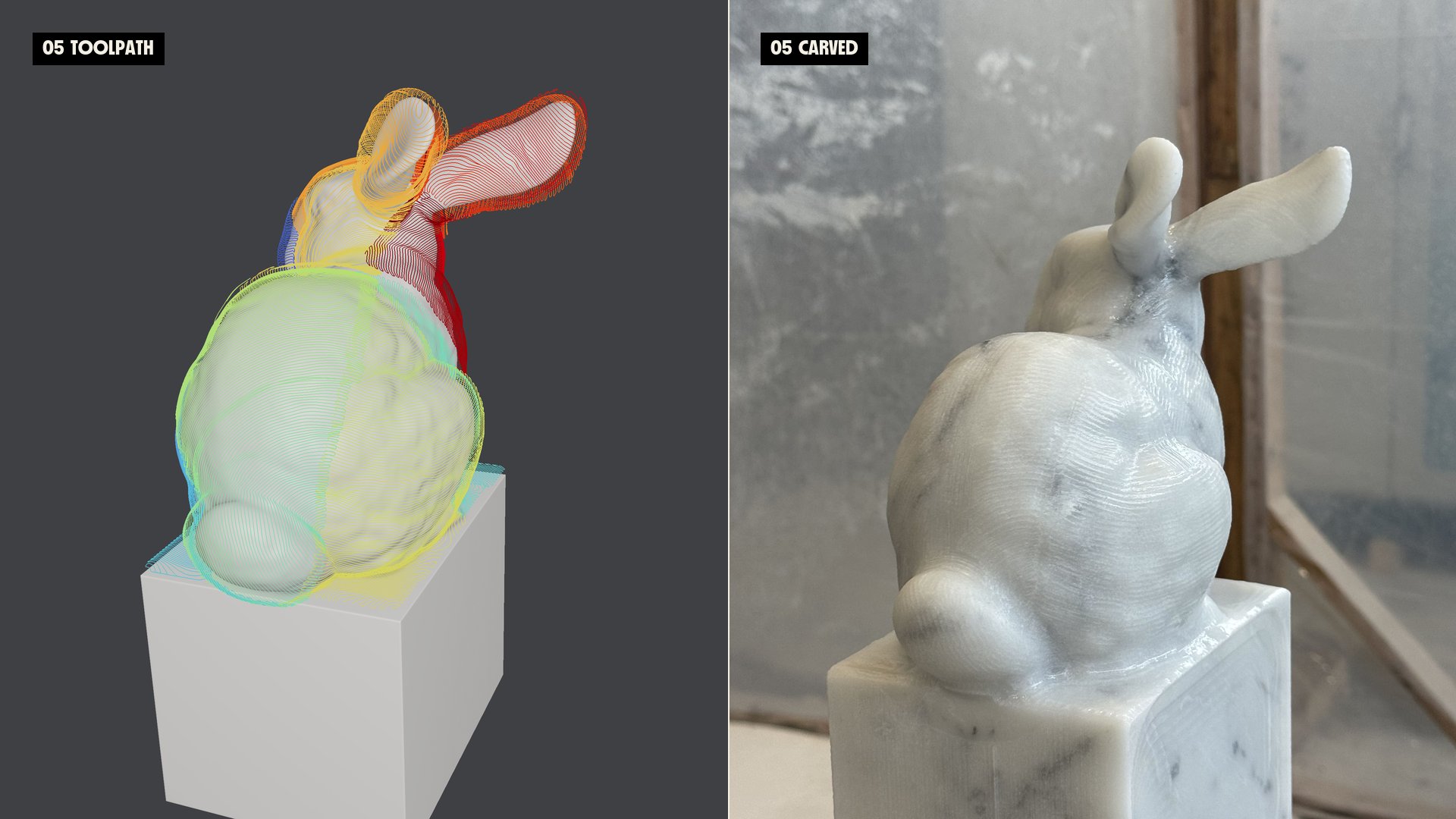
Within a segment, we generate the toolpath from geodesic distances. Euclidean distance is a straight line, which on a curved part would pass through the stone. Geodesic distance is measured along the surface. The result is a set of curvature-informed isolines on the bunny’s surface, evenly spaced in a way that is optimal for toolpathing.
Optimal toolpath connections
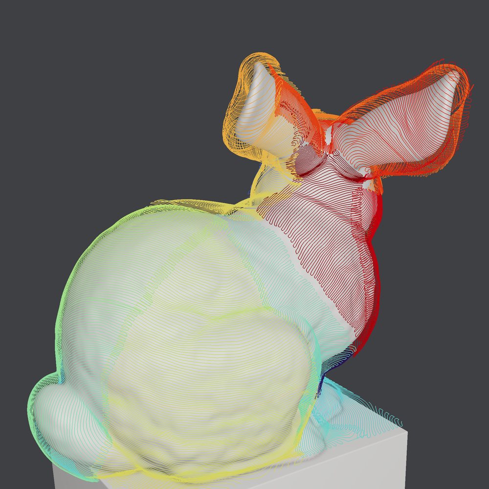
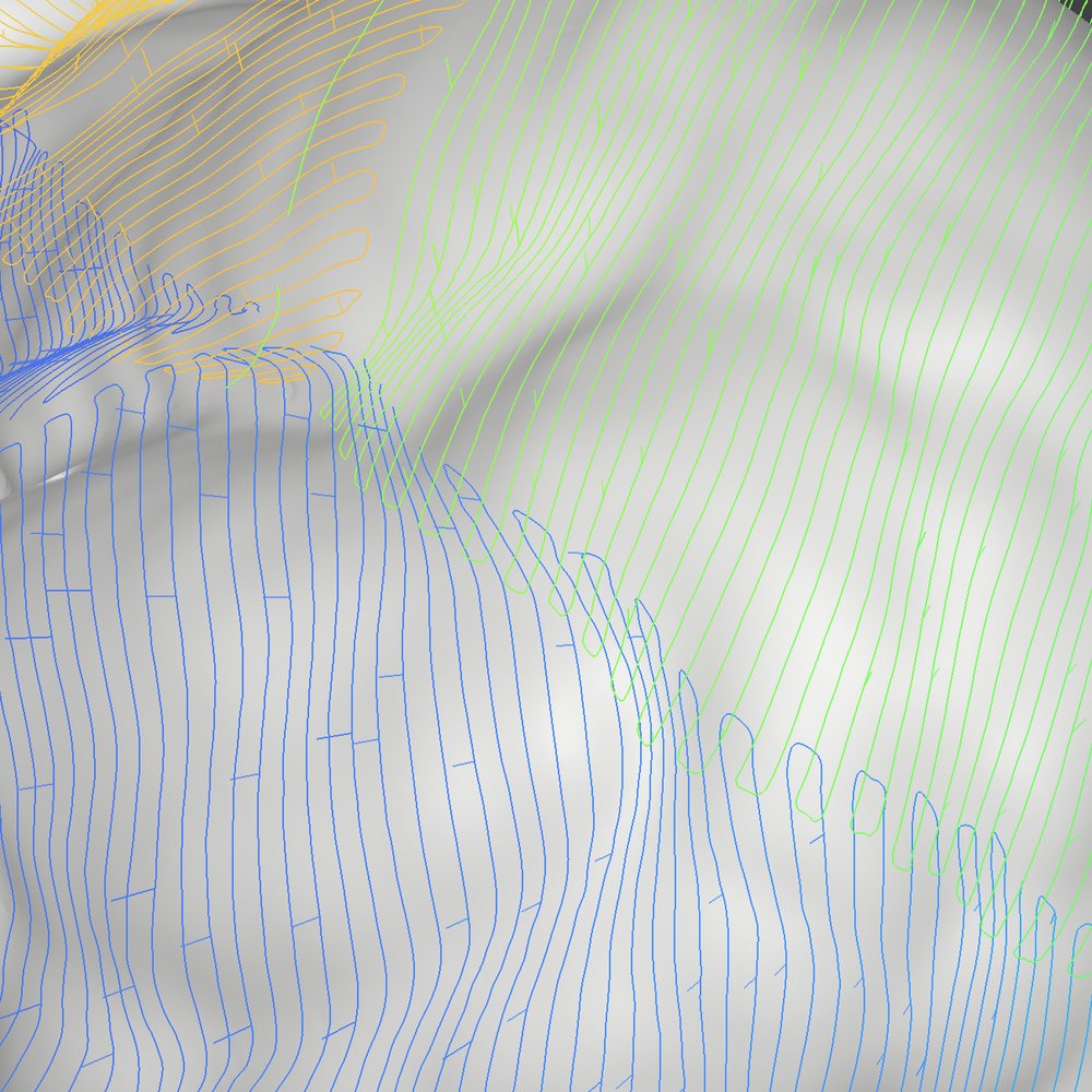
The isolines on their own are separate curves. We solve for a continuous, smooth, and optimally connected toolpath per segment, so the tool stays in the material and moves predictably instead of lifting and repositioning between passes.
Tool orientations and kinematics
Every segment also needs a tool orientation the robot can actually reach. We solve for collision-free tool orientations by segment, using access directions and tool tilt along the toolpath.
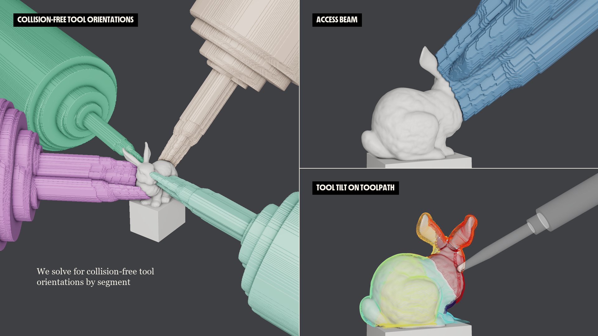
From there, we solve for safe, smooth, and collision-free joint angles for every point on the toolpath. In our proprietary toolpathing app below called Hilbert, we monitor joint angle health and visualize the kinematics limits of our various policies.
Simulation before stone
Because the whole pipeline is simulated, we can see the expected stone result before anything goes on the robot. That matters when the machine in question costs a million dollars.
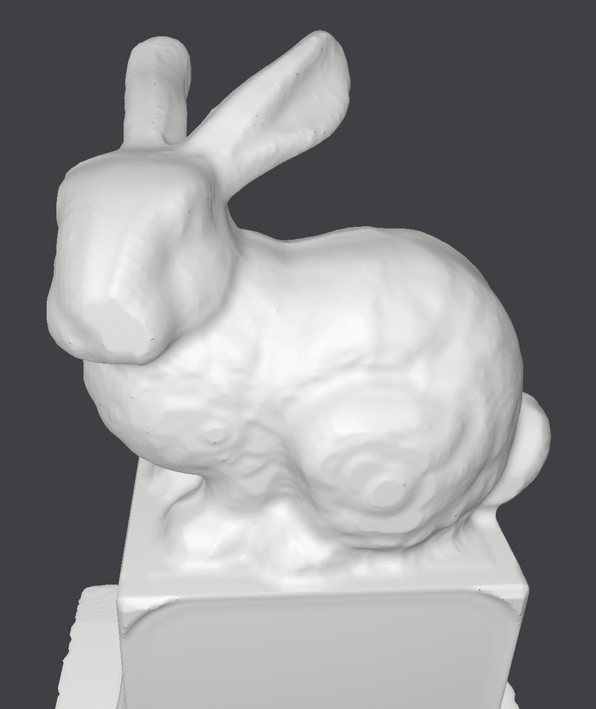 Roughing output
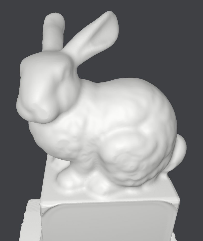 Toolpath 1
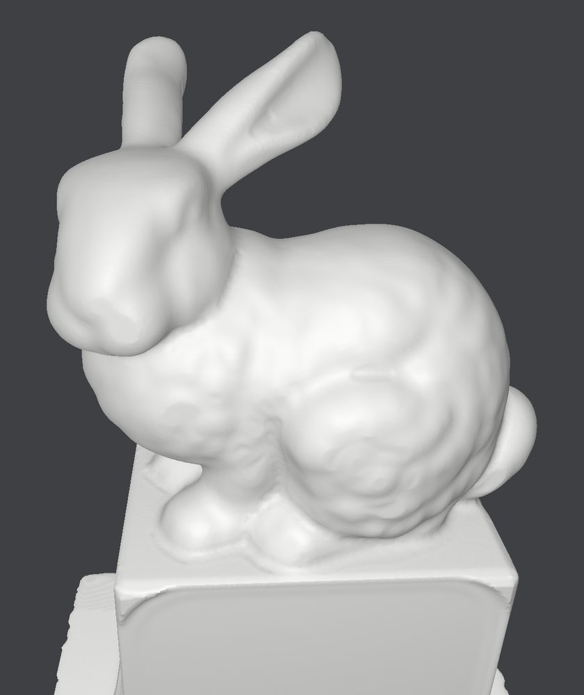 Toolpath 2
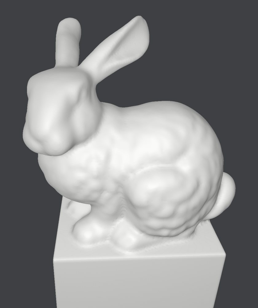 Final toolpath
Toolpath to carved
Here are the finishing toolpaths next to the carved marble, matched view for view.
Why we chose the Stanford Bunny as our debut sculpture
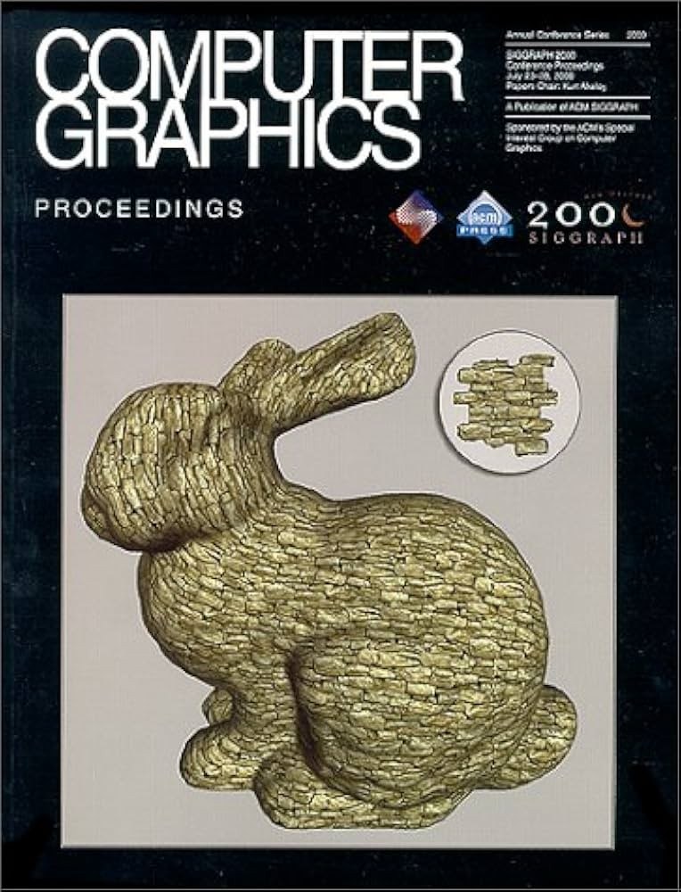
Since Greg Turk and Marc Levoy scanned a ceramic rabbit at Stanford in 1994, the Stanford Bunny has been graphics’ shared test model for three decades of research in reconstruction, mesh processing, and rendering. Our work would not have been possible without the computational geometry that grew up around it: signed distance fields, volumetric shape representations, and geodesic distances on surfaces, often tested on this very bunny. After milling ours in marble, we came across two old SIGGRAPH proceedings covers: the bunny rendered as stone in 2000, and a marble bust in 2001. We like to think this work makes us a small part of both graphics and robotics history, and we can’t wait to keep advancing the field.

You can learn more about our work at monumentallabs.co.